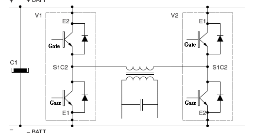
Single Phase Igbt Rectifier Circuit Diagram Inverter Circuit
Inverter circuit diagram using igbt Bridge inverter igbt single driver Igbt based single phase inverter
Topology of the single-phase PWM rectifier circuit. | Download
Diagram of the rc-igbt single phase voltage-source. Inverter phase circuit three 120 degree mode conduction diagram dc dilip raja nov Politica indietro skipper 3 phase inverter circuit pescatore
Vi characteristics of igbt explained
Igbt circuit exampleSolved for the following single phase rectifier circuit with Single phase igbt rectifier circuit diagramSingle phase rectifier.
Solved in the single-phase rectifier circuit of fig.Apa power supply berbasis moda frekuensi tinggi berbasis igbt Single-phase rectifier circuits on the control of the electric circuitSingle phase igbt inverter..

Topology of the single-phase pwm rectifier circuit.
A.power circuit diagram of an igbt based single phase fullbridgeIgbt berbasis rectifier sirkuit daya utama modul gambar frekuensi tinggi skematik 120° mode inverter – circuit diagram, operation and formulaIgbt ups circuit diagram.
How to set phase delay for a three phase igbt rectifier – valuable techIgbt inverter wiring danyk sg3525 Inverter circuit diagram mode 120 operation phase three bridge power formula shown below figurePower circuit diagram of an igbt based single phase full-bridge.

About igbts
Electrical – igbt rectifier gate voltage – valuable tech notesPower circuit diagram of an igbt based single phase full-bridge 1 phase bridge rectifier + 3 phase inverter igbtThree phase inverter circuit diagram.
Phase inverter wiring diagramVfd circuit motor phase pwm igbt inverter speed vsd controller drives skema rangkaian induksi pengaturan kecepatan teknik vokasi vfds frecuencia Three phase inverter circuit diagram – diy electronics projectsAc motor speed controller circuit.

Solved figure2 the above single-phase rectifier (fig 2) is
Igbt rectifier: working, features and important applicationsIgbt inverter circuit diagram pdf Inverter igbt researchgate implementation microgridIgbt structure.
Circuit model of rectifier with single-phase interruption.Electronic – single phase rectifier – valuable tech notes Igbt inverterIgbt inverter.

Rectifier pwm topology
Inverter igbt power diagrams diode supplyIgbt based rectifier circuit diagram Igbt explained obtaining resistorPower circuit diagram of an igbt based single phase full-bridge.
.


Igbt Circuit Example - IOT Wiring Diagram

About IGBTs | TechWeb

120° Mode Inverter – Circuit Diagram, Operation and Formula
Igbt Inverter Circuit Diagram Pdf - Home Wiring Diagram

Apa Power Supply Berbasis Moda Frekuensi Tinggi Berbasis IGBT

Three Phase Inverter Circuit Diagram - 120 Degree and 180 Degree

How to set phase delay for a three phase igbt rectifier – Valuable Tech